Installation And Maintenance Guide
START UP CAUTION
If a shut-off device is installed in the discharge pipe, make sure that the unit is NOT operated with the shut-off device closed.
Before starting up the Blower unit, observe the values specified on the label. Specifications on the drive-motor nominal current apply at a gas entry and ambient temperature of +40 Degree [104 Degree F]
Adjust the motor circuit breaker to the drive motor nominal current.
Check direction of rotation, the intended rotating direction of the shaft is marked with arrows on the Blower housing.
The gas delivery direction is marked with arrows on the inlet and discharge connections.
Make sure the pipes/hoses on the inlet and discharge connections are properly connected.
Switch the pump-motor unit on briefly and then off again.
Compare the actual rotating direction of the external fan with the intended shaft rotating direction of the external fan with the intended shaft rotating direction indicated with the arrows shortly before the Blower unit comes to a standstill.
If necessary reverse the direction of rotation of the motor.
Check operating speeds :
Observe the operating speed specified on the label this may not be exceeded, as otherwise the noise radiation, vibration behavior, grease consumption duration and bearing change interval will worsen. To prevent damage as a result of higher speeds, it may be necessary to inquire with us as to the maximum speed.
Start-up and shut down
Start-up
Open shut-off device in intake/discharge pipe Switch on power supply for drive motor.
Shut down
Switch off power supply for drive motor Close shut-off device in intake/discharge pipe.
Preparing for shut down or longer standstill
Prior to shut-down or longer standstill, proceed as follows:
- Switch off the Blower unit.
- Close shut-off device in inlet and pressure line if installed.
- Disconnect Blower unit from power supply.
- Release pressure.
- When doing so, open pipes/hoses slowly and carefully so that the vacuum or gauge pressure in the pump-motor unit can be released.
- Remove pipes/hoses.
- Provide mufflers on inlet and discharge side with sealing plugs
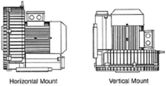
ILLUSTRATIONS
See following illustrations for better understanding of some of above instructions.
MOUNTING